//------------------------------------------------------------
int xPin = 2; // select the input pin for the potentiometer
int gyroPin = 1;
int steerPin = 3;
int ledPin = 13; // select the pin for the LED
int pwmPinL = 9;
int pwmPinR = 10;
int enPin = 7;
float angle = 0;
float angle_old = 0;
float angle_dydx = 0;
float angle_integral = 0;
float balancetorque = 0;
float rest_angle = 0;
float currentspeed = 0;
int steeringZero = 0;
int steering = 0;
int steeringTemp = 0;
float p = 8; //2
float i = 0; //0.005
float d = 1300; //1000
float gyro_integration = 0;
float xZero = 0;
int gZero = 445; //this is always fixed, hence why no initialisation routine
unsigned long time, oldtime;
int pwmL;
int pwmR;
boolean over_angle = 0;
void setup() {
unsigned int i = 0;
unsigned long j = 0; //maximum possible value of j in routine is 102300 (100*1023)
pinMode(ledPin, OUTPUT); // declare the ledPin as an OUTPUT
Serial.begin(115200);
analogReference(EXTERNAL);
//----------------------------------------------------
TCCR1B = TCCR1B & 0b11111000 | 0x01;
analogWrite(pwmPinL,127);
analogWrite(pwmPinR,127);
digitalWrite(enPin,HIGH);
pinMode(enPin,OUTPUT);
digitalWrite(enPin,LOW);
//-----------------------------------------------------
delay(100);
for (i = 0; i < j =" j" steeringzero =" analogRead(steerPin);" xzero =" j/100;" oldtime =" micros();" time =" micros();">= (oldtime+5000)){
oldtime = time;
calculateAngle();
steering = (analogRead(steerPin) - steeringZero)/(15+(abs(angle)*8));
//-----OVER ANGLE PROTECTION-----
if (angle > 20 || angle < -20) { digitalWrite(enPin,HIGH); over_angle = 1; delay(500); } //-----END----- if (over_angle) { //if over_angle happened, give it a chance to reset when segway is level if (angle <> -1) {
digitalWrite(enPin, LOW);
over_angle = 0;
}
}
else {
//-----calculate rest angle-----
if (currentspeed > 10)
{
rest_angle = 0;
//-----END-----
angle_integral += angle;
balancetorque = ((angle+rest_angle)*p) + (angle_integral*i) + (angle_dydx*d);
angle_dydx = (angle - angle_old)/200; //now in degrees per second
angle_old = angle;
currentspeed += (balancetorque/200);
pwmL = (127 + balancetorque + steering);
//-----COERCE-----
if (pwmL < pwml =" 0;"> 255)
pwmL = 255;
//-----END-----
pwmR = (127 - balancetorque + steering);
//-----COERCE-----
if (pwmR < pwmr =" 0;"> 255)
pwmR = 255;
//-----END-----
analogWrite(pwmPinL, pwmL);
analogWrite(pwmPinR, pwmR);
}
}
}
void calculateAngle() {
//Analogref could be as small as 2.2V to improve step accuracy by ~30%
//uses small angle approximation that sin x = x (in rads). maybe use arcsin x for more accuracy?
//analogref is off the gyro power supply voltage, and routine is calibrated for 3.3V. maybe run acc/gyro/ref off 1 3.3V regulator, an
//accurately measure that.
//routine runs at 200hz because gyro maximum response rate = 200hz
float acc_angle = 0;
float gyro_angle = 0;
acc_angle = (((analogRead(xPin)-xZero)/310.3030)*(-57.2958);
gyro_angle = ((analogRead(gyroPin) - gZero)*4.8099)/200;
gyro_integration = gyro_integration + gyro_angle; //integration of gyro and gyro angle calculation
angle = (gyro_integration * 0.99) + (acc_angle * 0.01); //complementary filter
gyro_integration = angle; //drift correction of gyro integration
}
Monday, 2 November 2009
Arduino code
I see some of you are interested in the code.. well here it is, unedited:
Monday, 29 June 2009
Saturday, 20 June 2009
Wednesday, 3 June 2009
ESCs, power wiring and fuses...
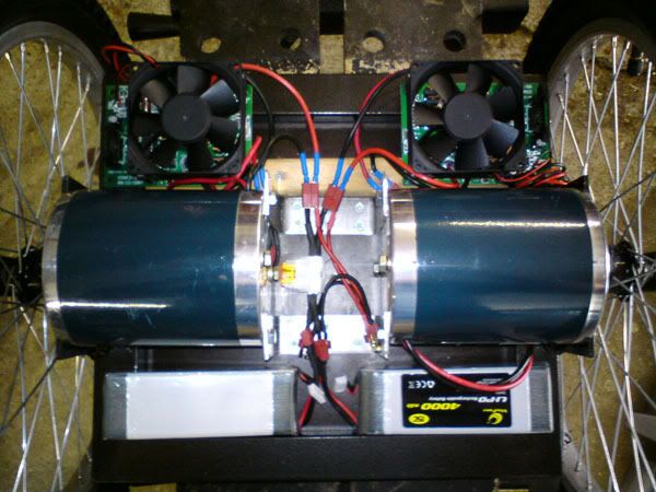
At the top are the 2 electronic speed controllers, in the centre are the 2 fuses (1 40amp fuse for each controller). At the bottom is a test placement of the batteries, I've yet to make a mounting for them.
Sunday, 26 April 2009
OSMC
I have finished the Open Source Motor Controller boards:
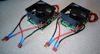
I am using Deans T Connectors which I've read can handle upto 100A, but I doubt this could be sustained, but it does have the fact the body of the connector is made of nylon style plastic, not acrylic, so heat wouldn't deform it. So 100A could well be possible.

I am using Deans T Connectors which I've read can handle upto 100A, but I doubt this could be sustained, but it does have the fact the body of the connector is made of nylon style plastic, not acrylic, so heat wouldn't deform it. So 100A could well be possible.
Sunday, 18 January 2009
Calculating platform angle
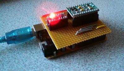
I have written arduino code to calculate the platform angle and it works perfectly!
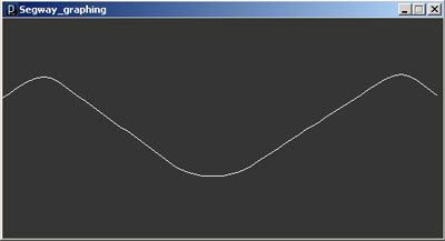
This is a graph made in Processing which is taking the angle calculated by the arduino from the serial port. I am oscillating the board quickly.
I am using the complementary filter approach documented by alot of balancing robots. The actual code is something like:
val = ((((analogRead(xPin)-xZero)/148.48)* 180/3.1415926535897932384626433832795))*-1); //accelerometer angle calculation
valG = valG + ((analogRead(gyroPin) - gZero)*4.8099347014925373134328358208962)/200; //integration of gyro and gyro angle calculation
angle = (val * 0.005) + (valG * 0.995); //complementary filter
valG = angle; //drift correction of gyro integration
I can tell it works as intended, because if i rotate the board flat on the table, the gyro senses it, whilst the accelerometer is still flat, so you see it increase and then decay slowly back to zero, rather like a capacitor discharge curve. This shows the accelerometer correcting the gyro's 'drift'.
Friday, 16 January 2009
Riding it without power!
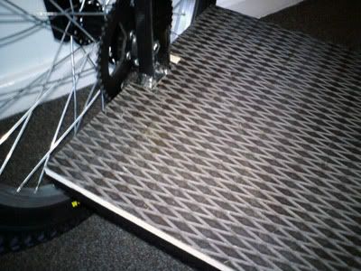
I quickly cut up a bit of plywood to stand on, and was tempted to stand on it.
To my suprise, using my hands on the tires to balance me, I can actually move around and maintain balance. Although it probably helps that I can ride a unicycle and have those skills!
This is thanks to the weight of the motors to counterbalance me though!
To my suprise, using my hands on the tires to balance me, I can actually move around and maintain balance. Although it probably helps that I can ride a unicycle and have those skills!
This is thanks to the weight of the motors to counterbalance me though!
Thursday, 15 January 2009
Frame Done!
I have added the motor mounts and painted the frame with Black Hammerite.
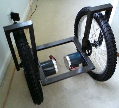
A great thing about having the platform below the wheel axis is the inherant stability, evident by the fact that it stands by itself!
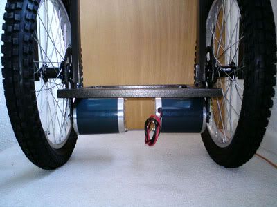
The ground clearance is pretty good too!
Now I take a break from frame building and focus on the electronics.

A great thing about having the platform below the wheel axis is the inherant stability, evident by the fact that it stands by itself!

The ground clearance is pretty good too!
Now I take a break from frame building and focus on the electronics.
Monday, 12 January 2009
Almost Completed Frame
After lots of hacksawing...
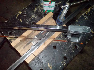
I have finally finished the basic frame.
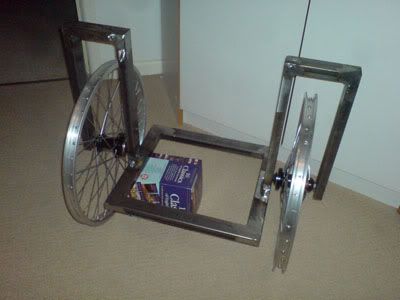
The plan next is to weld on the motor mounts, sand down the frame and spray it in black textured paint to give a tough and attractive finish.

I have finally finished the basic frame.

The plan next is to weld on the motor mounts, sand down the frame and spray it in black textured paint to give a tough and attractive finish.
Tuesday, 6 January 2009
Frame Base
I welded together the base of the frame tonight, interesting feeling is having heat in your hands and 0 degrees celsius elsewhere, it was cold outside tonight!
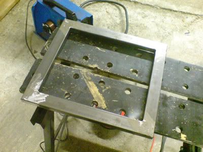
I'll be doing the wheel support arches when I receive the wheels to confirm measurements.

I'll be doing the wheel support arches when I receive the wheels to confirm measurements.
Motors
I got the 750W motors today from Technobots.
One runs at 1.5A idle (at 24V) and the other at 1.8A idle, probably due to manufacturing tolerances. Maybe I'll have problems with tracking straight when its finished?
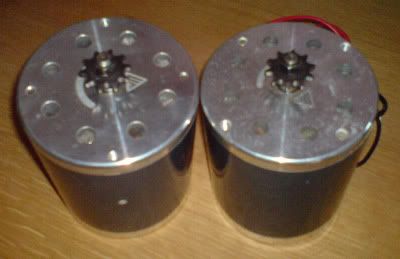
One runs at 1.5A idle (at 24V) and the other at 1.8A idle, probably due to manufacturing tolerances. Maybe I'll have problems with tracking straight when its finished?

Monday, 5 January 2009
Disc Mount Sprockets
I received the disc mount sprockets today:
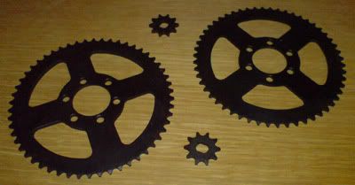
Hopefully tomorrow will bring 2 front 20" disc hub quick release wheels and then progress will be possible!

Hopefully tomorrow will bring 2 front 20" disc hub quick release wheels and then progress will be possible!
Saturday, 3 January 2009
Accurate Frame CAD Drawing
I found Google Sketchup to be very hard to use and therefore I couldn't create a decent CAD drawing. I transferred to using Solidworks at my university and drafted this:
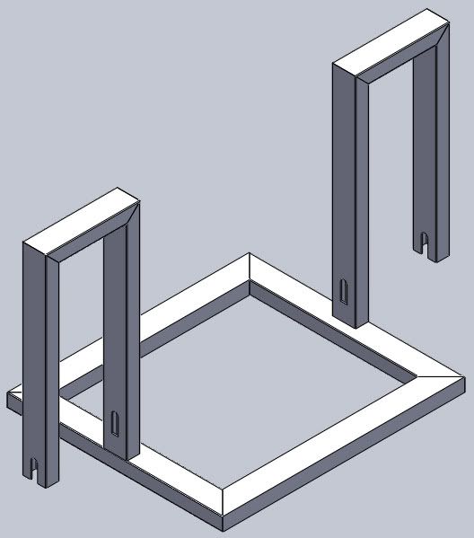
And rendered this:
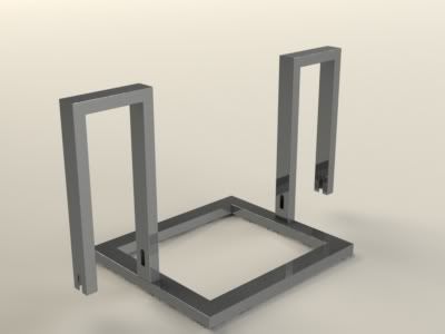
Big Frame Picture
Mockup with Tires

And rendered this:

Big Frame Picture
Mockup with Tires
Thursday, 1 January 2009
Initial CAD Drawing
I knocked up a concept CAD drawing in Google Sketchup to get a feel of the design. Having tweaked it, I'm satisfied that it will be good.
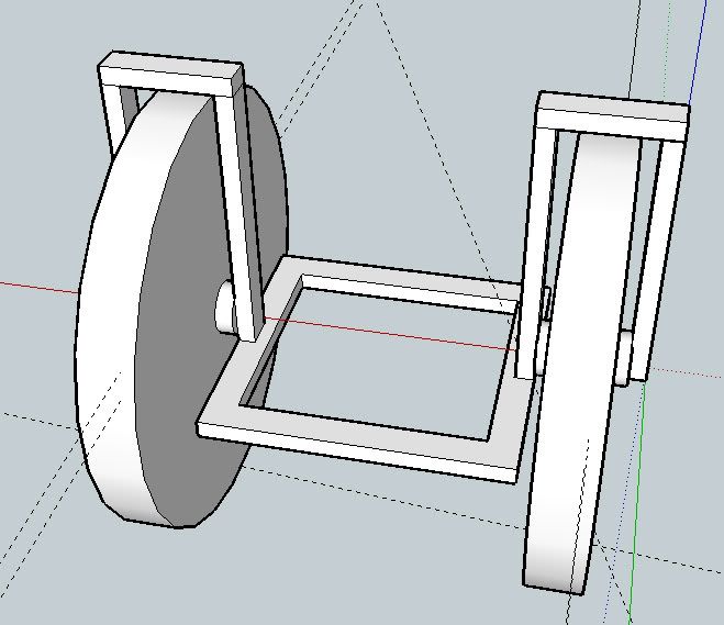
Points to note:
- The foot platform is below the centre of the wheels. This may help its stability, but more importantly it reduces the step up and travelling height.
- The wheels are supported from both sides. Whilst this may have an unsightly look to the frame, it means the design is cheaper as it can use standard bicycle parts.
- The overall width is 600mm, this was my target width to easily drive through doorways.
- When the motors are installed, there should be ground clearance between 75-100mm.
Subscribe to:
Comments (Atom)
