//------------------------------------------------------------
int xPin = 2; // select the input pin for the potentiometer
int gyroPin = 1;
int steerPin = 3;
int ledPin = 13; // select the pin for the LED
int pwmPinL = 9;
int pwmPinR = 10;
int enPin = 7;
float angle = 0;
float angle_old = 0;
float angle_dydx = 0;
float angle_integral = 0;
float balancetorque = 0;
float rest_angle = 0;
float currentspeed = 0;
int steeringZero = 0;
int steering = 0;
int steeringTemp = 0;
float p = 8; //2
float i = 0; //0.005
float d = 1300; //1000
float gyro_integration = 0;
float xZero = 0;
int gZero = 445; //this is always fixed, hence why no initialisation routine
unsigned long time, oldtime;
int pwmL;
int pwmR;
boolean over_angle = 0;
void setup() {
unsigned int i = 0;
unsigned long j = 0; //maximum possible value of j in routine is 102300 (100*1023)
pinMode(ledPin, OUTPUT); // declare the ledPin as an OUTPUT
Serial.begin(115200);
analogReference(EXTERNAL);
//----------------------------------------------------
TCCR1B = TCCR1B & 0b11111000 | 0x01;
analogWrite(pwmPinL,127);
analogWrite(pwmPinR,127);
digitalWrite(enPin,HIGH);
pinMode(enPin,OUTPUT);
digitalWrite(enPin,LOW);
//-----------------------------------------------------
delay(100);
for (i = 0; i < j =" j" steeringzero =" analogRead(steerPin);" xzero =" j/100;" oldtime =" micros();" time =" micros();">= (oldtime+5000)){
oldtime = time;
calculateAngle();
steering = (analogRead(steerPin) - steeringZero)/(15+(abs(angle)*8));
//-----OVER ANGLE PROTECTION-----
if (angle > 20 || angle < -20) { digitalWrite(enPin,HIGH); over_angle = 1; delay(500); } //-----END----- if (over_angle) { //if over_angle happened, give it a chance to reset when segway is level if (angle <> -1) {
digitalWrite(enPin, LOW);
over_angle = 0;
}
}
else {
//-----calculate rest angle-----
if (currentspeed > 10)
{
rest_angle = 0;
//-----END-----
angle_integral += angle;
balancetorque = ((angle+rest_angle)*p) + (angle_integral*i) + (angle_dydx*d);
angle_dydx = (angle - angle_old)/200; //now in degrees per second
angle_old = angle;
currentspeed += (balancetorque/200);
pwmL = (127 + balancetorque + steering);
//-----COERCE-----
if (pwmL < pwml =" 0;"> 255)
pwmL = 255;
//-----END-----
pwmR = (127 - balancetorque + steering);
//-----COERCE-----
if (pwmR < pwmr =" 0;"> 255)
pwmR = 255;
//-----END-----
analogWrite(pwmPinL, pwmL);
analogWrite(pwmPinR, pwmR);
}
}
}
void calculateAngle() {
//Analogref could be as small as 2.2V to improve step accuracy by ~30%
//uses small angle approximation that sin x = x (in rads). maybe use arcsin x for more accuracy?
//analogref is off the gyro power supply voltage, and routine is calibrated for 3.3V. maybe run acc/gyro/ref off 1 3.3V regulator, an
//accurately measure that.
//routine runs at 200hz because gyro maximum response rate = 200hz
float acc_angle = 0;
float gyro_angle = 0;
acc_angle = (((analogRead(xPin)-xZero)/310.3030)*(-57.2958);
gyro_angle = ((analogRead(gyroPin) - gZero)*4.8099)/200;
gyro_integration = gyro_integration + gyro_angle; //integration of gyro and gyro angle calculation
angle = (gyro_integration * 0.99) + (acc_angle * 0.01); //complementary filter
gyro_integration = angle; //drift correction of gyro integration
}
Monday 2 November 2009
Arduino code
I see some of you are interested in the code.. well here it is, unedited:
Monday 29 June 2009
Saturday 20 June 2009
Wednesday 3 June 2009
ESCs, power wiring and fuses...
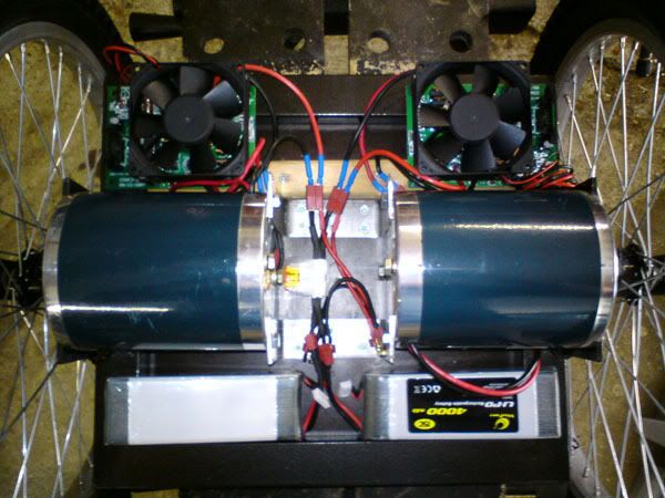
At the top are the 2 electronic speed controllers, in the centre are the 2 fuses (1 40amp fuse for each controller). At the bottom is a test placement of the batteries, I've yet to make a mounting for them.
Sunday 26 April 2009
OSMC
I have finished the Open Source Motor Controller boards:
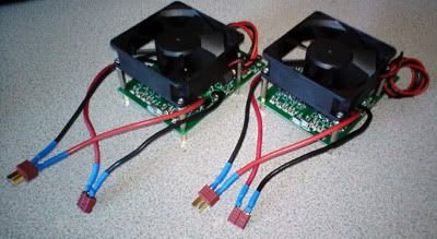
I am using Deans T Connectors which I've read can handle upto 100A, but I doubt this could be sustained, but it does have the fact the body of the connector is made of nylon style plastic, not acrylic, so heat wouldn't deform it. So 100A could well be possible.
I am using Deans T Connectors which I've read can handle upto 100A, but I doubt this could be sustained, but it does have the fact the body of the connector is made of nylon style plastic, not acrylic, so heat wouldn't deform it. So 100A could well be possible.
Sunday 18 January 2009
Calculating platform angle
I have written arduino code to calculate the platform angle and it works perfectly!
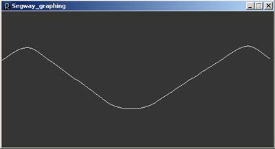
This is a graph made in Processing which is taking the angle calculated by the arduino from the serial port. I am oscillating the board quickly.
I am using the complementary filter approach documented by alot of balancing robots. The actual code is something like:
val = ((((analogRead(xPin)-xZero)/148.48)* 180/3.1415926535897932384626433832795))*-1); //accelerometer angle calculation
valG = valG + ((analogRead(gyroPin) - gZero)*4.8099347014925373134328358208962)/200; //integration of gyro and gyro angle calculation
angle = (val * 0.005) + (valG * 0.995); //complementary filter
valG = angle; //drift correction of gyro integration
I can tell it works as intended, because if i rotate the board flat on the table, the gyro senses it, whilst the accelerometer is still flat, so you see it increase and then decay slowly back to zero, rather like a capacitor discharge curve. This shows the accelerometer correcting the gyro's 'drift'.
Subscribe to:
Posts (Atom)