Sunday 18 January 2009

Calculating platform angle

Photobucket

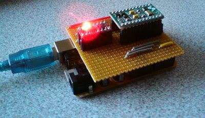
I have written arduino code to calculate the platform angle and it works perfectly!

Photobucket

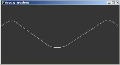
This is a graph made in Processing which is taking the angle calculated by the arduino from the serial port. I am oscillating the board quickly.

I am using the complementary filter approach documented by alot of balancing robots. The actual code is something like:

val = ((((analogRead(xPin)-xZero)/148.48)* 180/3.1415926535897932384626433832795))*-1); //accelerometer angle calculation

valG = valG + ((analogRead(gyroPin) - gZero)*4.8099347014925373134328358208962)/200; //integration of gyro and gyro angle calculation

angle = (val * 0.005) + (valG * 0.995); //complementary filter

valG = angle; //drift correction of gyro integration


I can tell it works as intended, because if i rotate the board flat on the table, the gyro senses it, whilst the accelerometer is still flat, so you see it increase and then decay slowly back to zero, rather like a capacitor discharge curve. This shows the accelerometer correcting the gyro's 'drift'.

Friday 16 January 2009

Riding it without power!

I quickly cut up a bit of plywood to stand on, and was tempted to stand on it.
To my suprise, using my hands on the tires to balance me, I can actually move around and maintain balance. Although it probably helps that I can ride a unicycle and have those skills!

This is thanks to the weight of the motors to counterbalance me though!

Thursday 15 January 2009

Frame Done!

I have added the motor mounts and painted the frame with Black Hammerite.

Photobucket

A great thing about having the platform below the wheel axis is the inherant stability, evident by the fact that it stands by itself!

Photobucket

The ground clearance is pretty good too!

Now I take a break from frame building and focus on the electronics.

Monday 12 January 2009

Almost Completed Frame

After lots of hacksawing...

Photobucket

I have finally finished the basic frame.

Photobucket

The plan next is to weld on the motor mounts, sand down the frame and spray it in black textured paint to give a tough and attractive finish.

Tuesday 6 January 2009

Frame Base

I welded together the base of the frame tonight, interesting feeling is having heat in your hands and 0 degrees celsius elsewhere, it was cold outside tonight!

Photobucket

I'll be doing the wheel support arches when I receive the wheels to confirm measurements.

Motors

I got the 750W motors today from Technobots.
One runs at 1.5A idle (at 24V) and the other at 1.8A idle, probably due to manufacturing tolerances. Maybe I'll have problems with tracking straight when its finished?

Photobucket

Monday 5 January 2009

Disc Mount Sprockets

I received the disc mount sprockets today:

Photobucket

Hopefully tomorrow will bring 2 front 20" disc hub quick release wheels and then progress will be possible!

Saturday 3 January 2009

Accurate Frame CAD Drawing

I found Google Sketchup to be very hard to use and therefore I couldn't create a decent CAD drawing. I transferred to using Solidworks at my university and drafted this:

Photobucket

And rendered this:

Photobucket

Big Frame Picture
Mockup with Tires

Thursday 1 January 2009

Initial CAD Drawing

I knocked up a concept CAD drawing in Google Sketchup to get a feel of the design. Having tweaked it, I'm satisfied that it will be good.

Photobucket

Points to note:

- The foot platform is below the centre of the wheels. This may help its stability, but more importantly it reduces the step up and travelling height.
- The wheels are supported from both sides. Whilst this may have an unsightly look to the frame, it means the design is cheaper as it can use standard bicycle parts.
- The overall width is 600mm, this was my target width to easily drive through doorways.
- When the motors are installed, there should be ground clearance between 75-100mm.